This only applies to Dato DUO synthesizers with serial numbers below 4630
Go to GitHub - datomusic/duo-imxrt · GitHub for updated instructions.
Here is how to adapt the firmware for the Dato DUO development prototype. These instructions are rough around the edges and bound to change while we fine tune the process.
What you need:
Hardware
- Dato DUO
- Micro USB cable / power supply
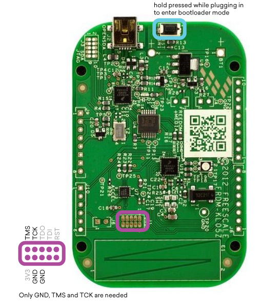
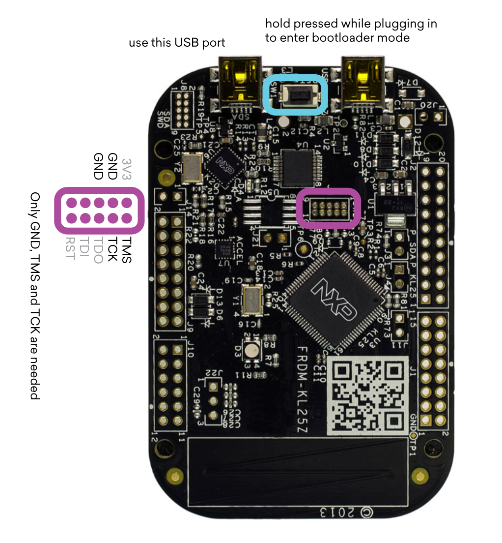
- SWD (Serial Wire Debug) programmer
- Cable to connect the programmer to the programming header on the DUO Brains
Software
The following is only tested on a Mac.
Install the Arduino IDE. 1.6.11 is recommended at this moment and can be downloaded from https://www.arduino.cc/en/Main/OldSoftwareReleases#previous
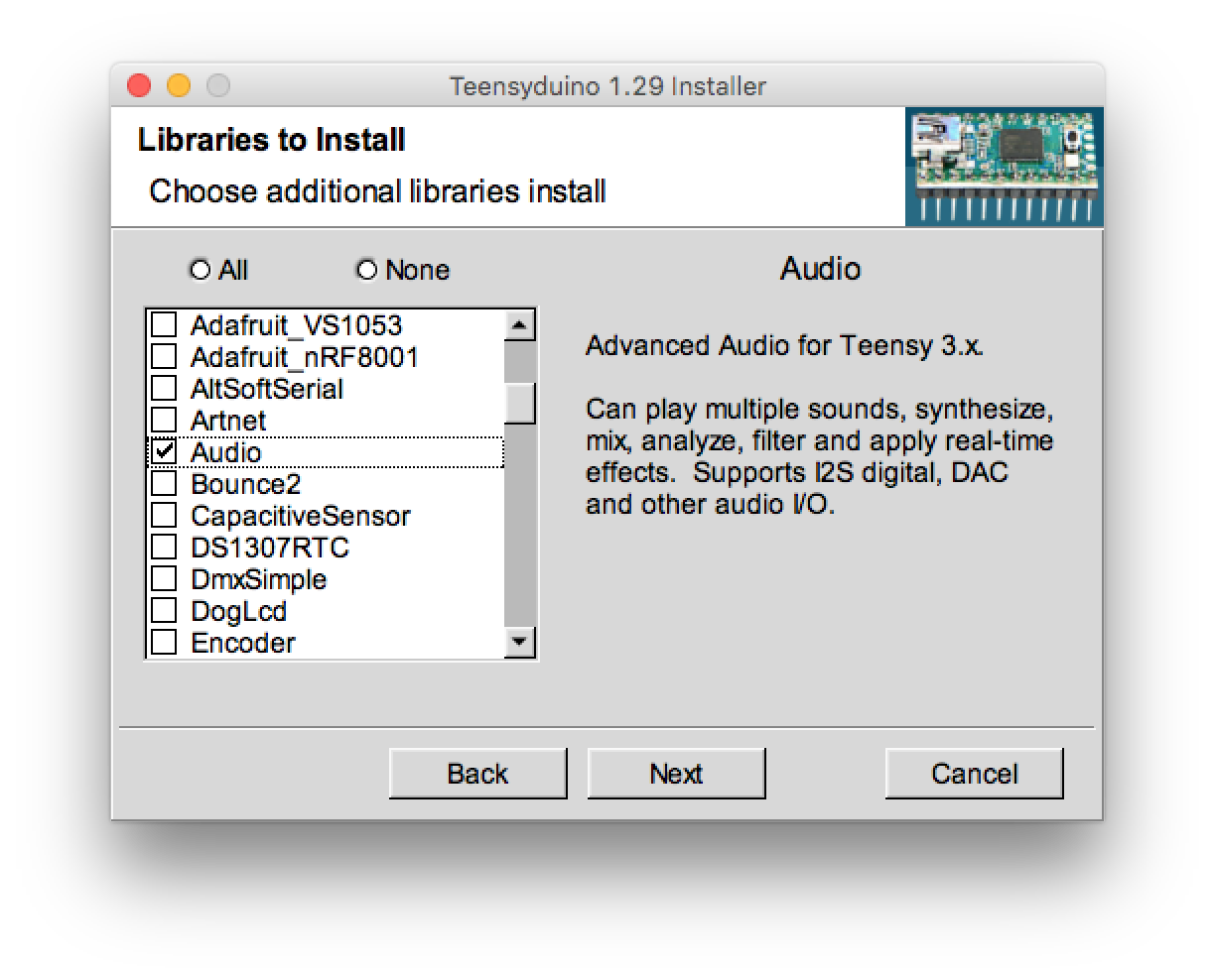
Install Teensyduino from Teensyduino - Add-on for Arduino IDE to use Teensy USB development board
Be sure to check the ‘Audio’, ‘FastLED’ and ‘Keypad’ libraries during installation.
Then open a terminal window, go to a folder where you want to place the DUO firmware files and clone the duo-firmware repository by typing the following commands:
git clone --recursive GitHub - datomusic/duo-firmware: Firmware for the Dato DUO · GitHub
If you forgot to add –recursive to your git clone, enter the git directory and type git submodule update --init --recursive to download the extra tools and libraries. You now have everything you need to start hacking the firmware.
Programming the Dato DUO
There is currently no way to upload code to the Dato DUO using the Arduino IDE. You will need to install OpenOCD 0.9.0 to program the DUO using an SWD programmer. On a Mac, install Homebrew from http://brew.sh/
/usr/bin/ruby -e “$(curl -fsSL https://raw.githubusercontent.com/Homebrew/install/master/install)”
and then install OpenOCD
brew install open-ocd
Compiling and uploading via the command line
Go to the duo-firmware folder (the cloned git repository): cd duo-firmware
Type make to compile the code. Connect the FRDM-KL05Z to a USB port, then power on the Dato DUO and type make flash to upload the code. If it fails, try typing make flash again.
Compiling and uploading via the Arduino IDE
You can also compile using the Arduino IDE. It’s not easier than the above method, though.
Turn on verbose mode in preferences.
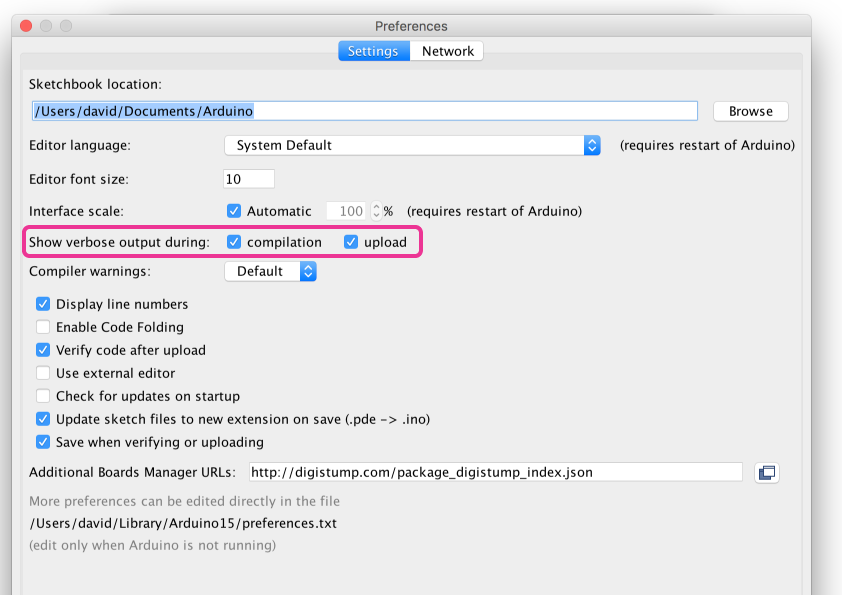
This allows us to grab the location of the compiled file later.
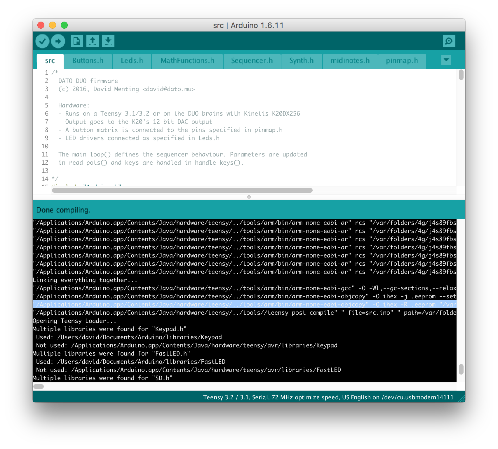
Choose boards → Teensy 3.2 72MHz as the target board. Click Verify (not upload) to compile the firmware. Once compiling is done, look for the line before ‘Opening Teensy Loader…’ in the verbose window. It should contain the path to the .elf and .hex files that were just created. The line should look something like this:
“/Applications/Arduino.app/Contents/Java/hardware/teensy/../tools/arm/bin/arm-none-eabi-objcopy” -O ihex -R .eeprom “/var/folders/4g/j4s89fbs1zsdks_pkxbtpt_40000gn/T/build34df3456261b7e01dee90fa86741109f.tmp/src.ino.elf” “/var/folders/4g/j4s89fbs1zsdks_pkxbtpt_40000gn/T/build34df3456261b7e01dee90fa86741109f.tmp/src.ino.hex”
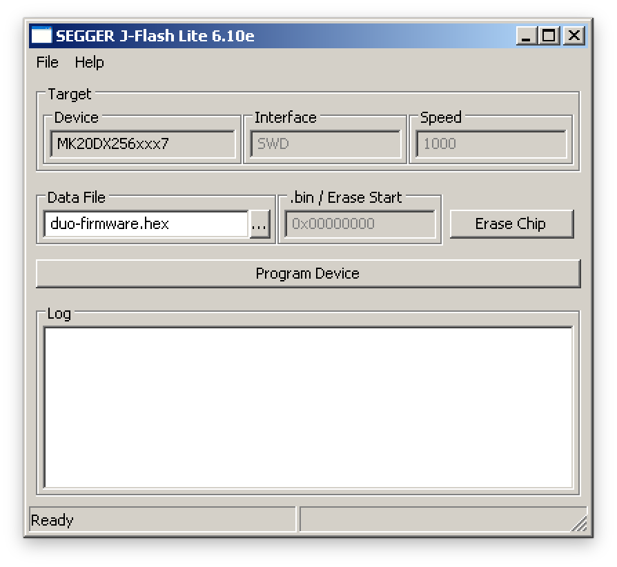
For Windows, download and install the Segger J-Link Software and Documentation pack from SEGGER - The Embedded Experts - Downloads - J-Link / J-Trace
Install the J-Link drivers first. Then use J-Link Flasher Lite with the .hex you either grabbed from the Arduino IDE or duo-firmware directory and Freescale MK20DX256xxx7 microcontroller profile to erase and program the device.
On the Mac, you can use the following command from the duo-firmware folder:
openocd -f openocd/openocd.cfg -c “program /var/folders/4g/j4s89fbs1zsdks_pkxbtpt_40000gn/T/build34df3456261b7e01dee90fa86741109f.tmp/src.ino.elf reset exit”
Replace the file path with the file path you grabbed from the Arduino IDE before.
This only applies to Dato DUO synthesizers with serial numbers below 4630
Go to GitHub - datomusic/duo-imxrt · GitHub for updated instructions.